|
Interaction Spaces: A camera-based system for scalable multi-touch 2D and 3D interaction on wall-sized, high-resolution displays | ||||||||
|
Multi-touch interaction has gained much traction in recent years. I have been researching systems for multi-touch/multi-point input since 2006, and along the way built one myself. This system forms the gesture-based interaction part of my Interaction Spaces system, and this page is here to show how a scalable multi-touch system can be built. The system is in use both at the Department of Computer Science at the University of Tromsø in Norway, and at the Lewis-Sigler Institute for Integrative Genomics at Princeton University in the US. The work you'll read about here is also documented in a series of papers:
|
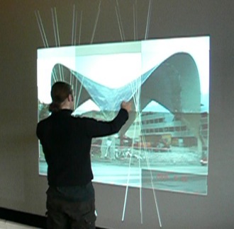
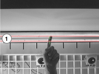
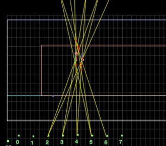
Fig. 1: A user (myself!) using the system. The white lines indicate what the cameras "see" and illustrates how the position of the hands can be triangulated. | |||||||
|
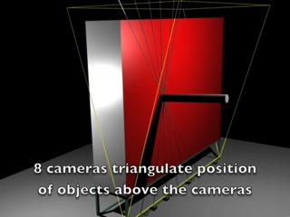
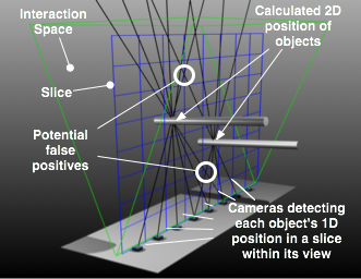
The system is also demonstrated in some videos that are available on YouTube: Design 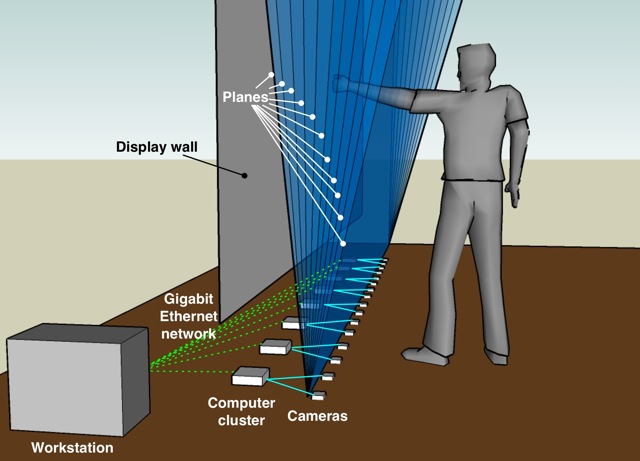 Fig. 1: The 3D interaction space is created using cameras mounted along the floor. The location of objects is determined by triangulating their location within each of the different planes illustrated above. By combining the 2D locations from each plane, a set of skeleton 3D objects result that can be interpreted by applications in different ways. The Interaction Spaces system is designed to provide scalable, multi-touch interaction to display walls. It creates an interaction space in front of the display wall in which it is possible to determine the position of objects (fingers, hands, arms, pens or similar) in both two and three dimensions (Figure 3). To do this, a set of cameras are mounted along the floor. The output from each camera is analyzed in order to separate foreground objects from the background. The result is a possibly empty set of 1D object positions per camera. Using triangulation, these 1D positions can be used to determine the 2D positions of each object. Figure 1 illustrates how conceptual "lines" can be drawn from each camera, passing through its corresponding object's position. With such lines from each camera, the resulting intersections indicate the positions of potential objects. To avoid false positives, an object must be detected by at least three cameras before it can be tracked. The reason for this is illustrated in Figure 5. When two or more objects are tracked, the use of just two cameras to locate an object will result in several "ghost objects" being acquired as well, at all the intersections with other cameras.
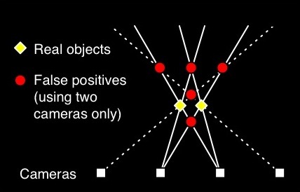
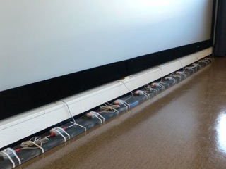
Fig. 5: The problem of false positives. Implementation The system has been implemented and is currently in use at the University of Tromsø and at Princeton University. The primary difference between the two implementations is that the version in Princeton only uses half as many cameras and computers. The reason for this is that it only needs to cover a display wall that is about half the width of the wall in Tromsø. The display wall in Tromsø measures 6 by 3 meters, and has a resolution of 7168x3072 pixels, while the Princeton wall measures 2.7x2 meters and has a resolution of 2048x1536 pixels. The Tromsø wall is built using 28 projectors, each driven by a single computer, whereas the Princeton wall uses 4 projector cubes, with each cube driven by one of four Mac minis (which are also used to drive the Interaction Spaces system). The remainder of this text will describe the implementation as it is in Tromsø, but using photos from both the Tromsø and Princeton installations. 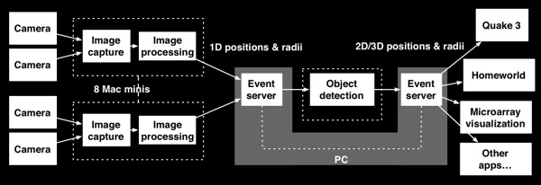 Fig. 6: The architecture of the system. The system is implemented using sixteen commodity web cameras and eight Mac minis, as shown in Figure 6. The system can easily be scaled to support wider or narrower display walls by adding or removing cameras and computers. The web cameras are Unibrain Fire-i firewire cameras, capable of delivering 640x480 grayscale images at 30 FPS. Each Mac mini is connected to two such cameras, and uses libdc1394 to communicate with the cameras. Apart from this, all the software is custom-developed. The software consists of the image processing software running on the Mac minis, and an object detector running on a separate computer (or one of the Mac minis - it doesn't really matter). The object detector gathers 1D object positions from each Mac mini, and then performs a triangulation step to determine 2D object positions.
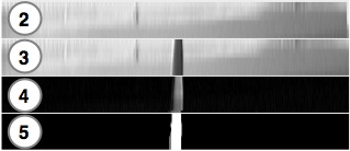
To support object detection not only in 2D, but in 3D as well, the system divides each camera image into a set of discrete slices. Each slice is then processed as for the 2D case, before the resulting 2D objects from each slice can be consolidated into one or several objects with 3D extent and position. A screenshot of the triangulation performed by the object detector can be seen in Figure 9. |
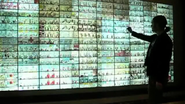
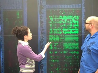
Event distribution All events in the system are handled by another custom component: The Shout event system. Shout is a network event system created specifically for delivering small input events between event providers and event consumers. The event system is instrumental in delivering 1D object positions from the image processing application running on each Mac mini, to the object detector, which in turn uses the event system to push events containing the position of detected objects to other applications. Some example applications include the two games Quake 3 Arena and Homeworld, as well as a number of other graphical demos and an application for visualizing genomic microarray data, shown in Figure 10.
More details I will update this page with more details as time permits. In general, the system is described in far more detail in the various papers listed above - this page is just meant as a quick overview of one approach to building a multi-touch system for wall-sized, high-resolution displays. |
|||||||